This project serves an industrial chemical processing system in Sweden. The production process requires multiple acidic raw materials to be stored separately, metered, transferred and diluted before being supplied continuously to downstream cleaning, surface treatment and other production equipment at a stable concentration. Residual liquids generated during equipment cleaning also need to be collected for reuse or transferred to a subsequent treatment system.
The customer required an interconnected group of FRP process tanks. Different tanks perform raw-material storage, solution preparation, supply buffering and cleaning-liquid collection functions. Together with metering pumps, agitators, transfer pumps, level instruments, vent lines and the control system, they form a complete chemical-liquid handling unit.
Based on the medium conditions, process flow, equipment layout and international transportation requirements provided by the customer, Yingnai completed the material review, structural design, interface confirmation, batch manufacturing, final inspection and delivery preparation for multiple FRP tanks.
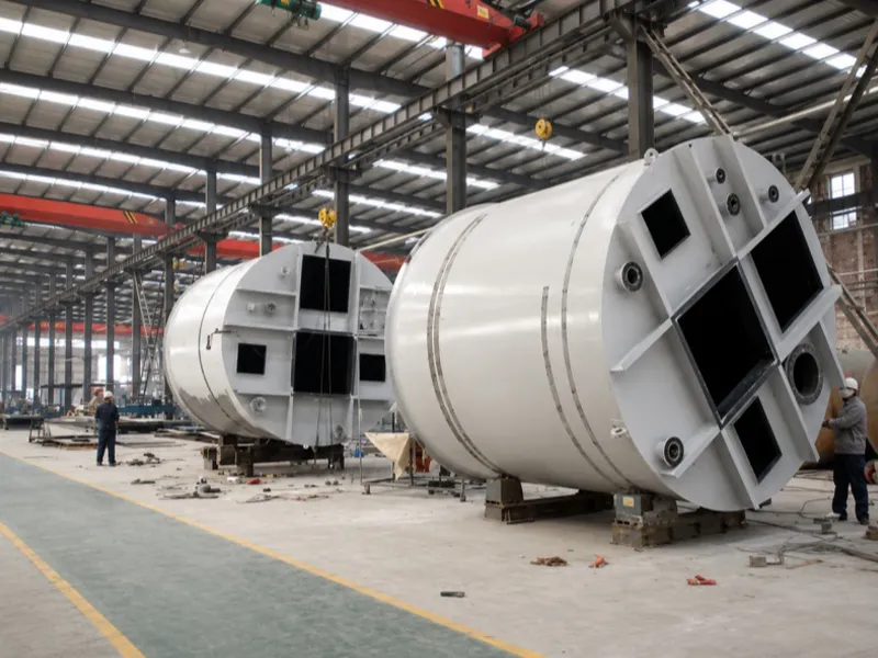
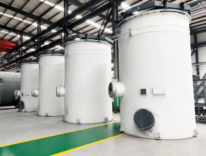
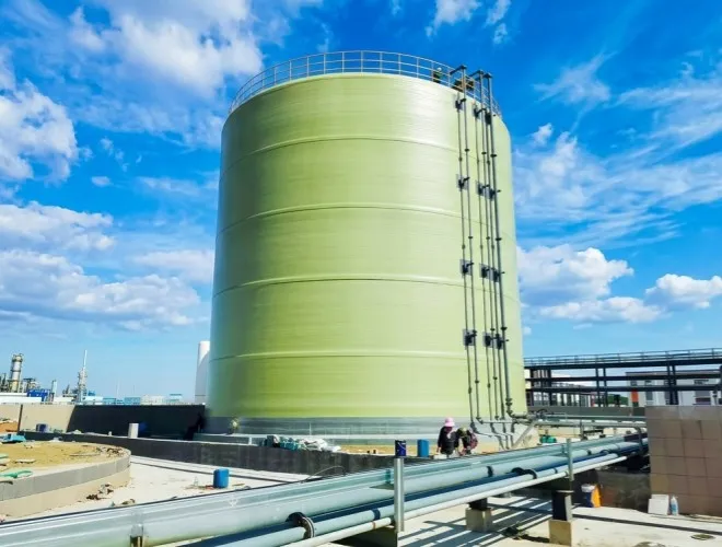
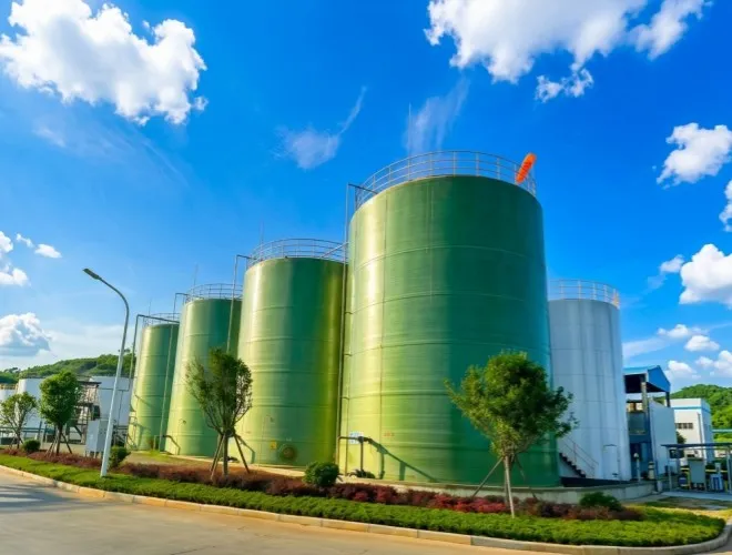
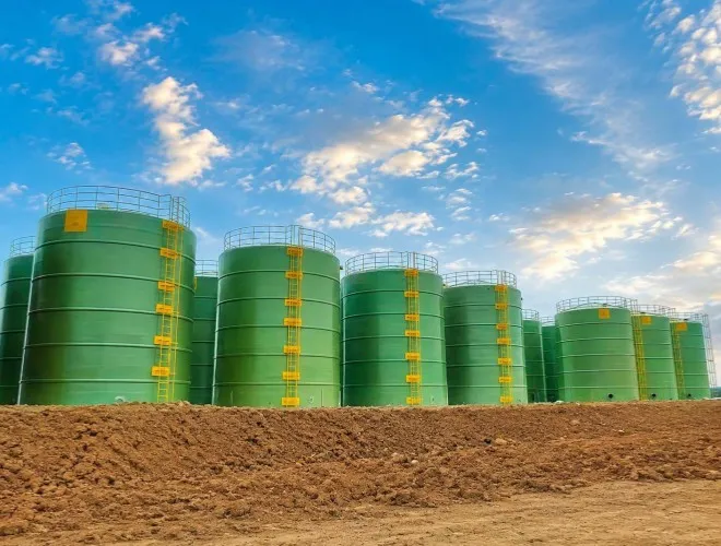
Based on raw-material consumption, batch preparation cycles, production-line supply requirements and available installation space, the project was equipped with multiple vertical FRP tanks for different process duties.
The principal equipment included:
The project included two FRP raw-material storage tanks, each with a capacity of approximately 20 m³, for separately storing acidic chemicals of different concentrations or for different process purposes.
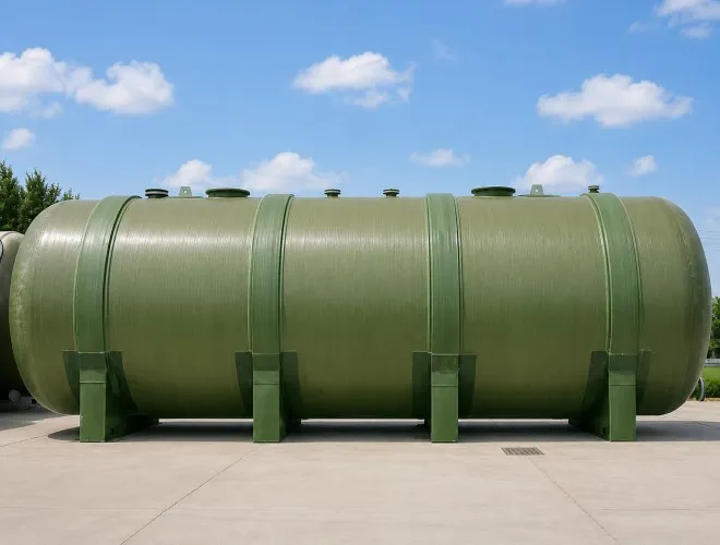
The tanks feature closed tops and flat-bottom construction and operate under atmospheric-pressure conditions. Each tank is equipped with an inlet, outlet, vent, overflow connection, bottom drain, manway and level-instrument connections. The tanks are connected to the unloading lines and chemical metering-pump system.
The project included two FRP preparation tanks, each with a capacity of approximately 15 m³, for mixing acidic raw materials with process water at specified ratios and achieving a uniform solution.
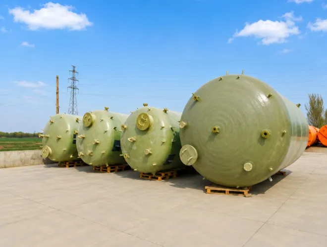
An agitator interface was provided at the top of each tank. Additional connections included raw-material inlets, process-water inlets, circulation connections, sampling ports and level-control interfaces. The tank roofs were locally reinforced according to the weight and operating conditions of the agitators.
The project included two FRP buffer tanks, each with a capacity of approximately 10 m³, for receiving the prepared process solution and supplying it continuously to downstream production equipment.
The buffer tanks provide intermediate storage between batch preparation and continuous consumption, reducing the effect of solution preparation, flow adjustments or short-term shutdowns on production-line operation.
The project included one FRP collection tank with a capacity of approximately 8 m³ for collecting equipment-cleaning liquid, pipeline drainage and reusable residual process solution.
Depending on the inspection results, the collected liquid can be returned to the preparation system for reuse or transferred to a designated treatment unit, reducing uncontrolled discharge of chemical liquids.
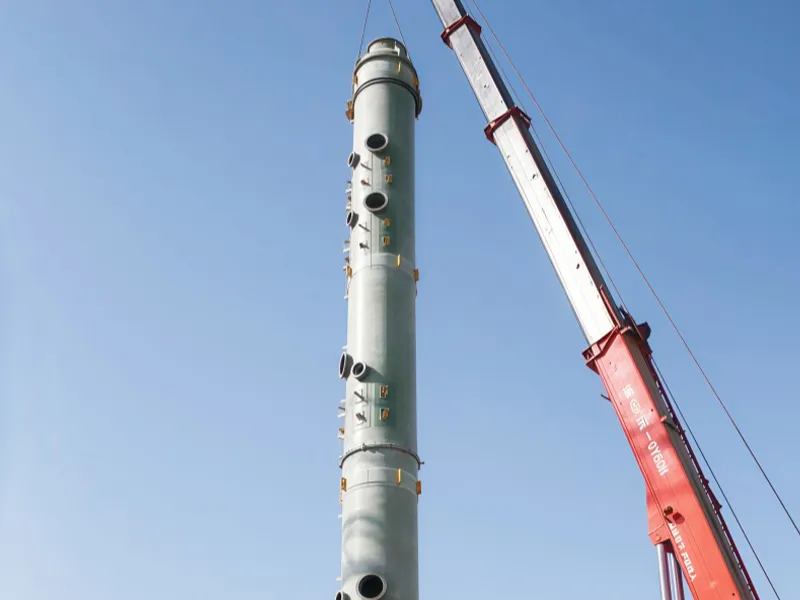
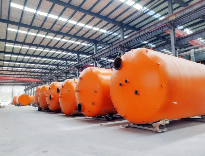
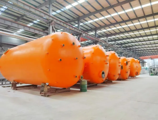
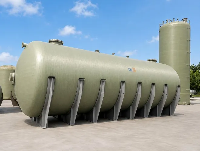
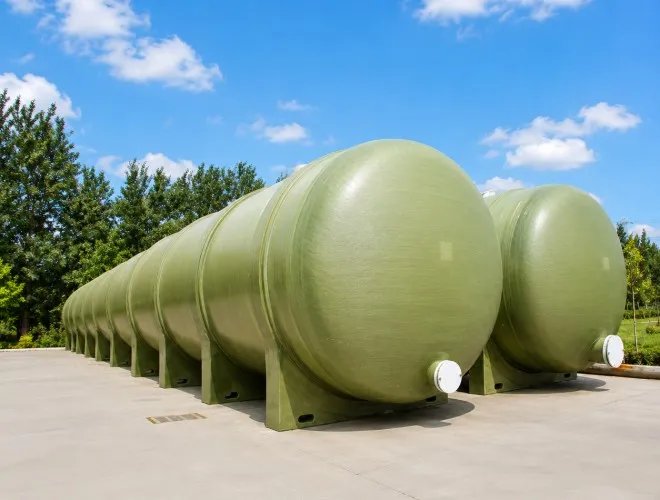
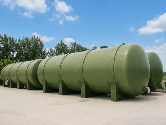
The complete project included seven FRP tanks with a combined capacity of approximately 100 m³. Tank diameters ranged from approximately 1.8 to 2.6 m, while overall heights ranged from approximately 3.5 to 6 m.
Each tank was configured with a different wetted laminate and accessory arrangement according to its contact medium, process function and interface conditions. The units were not simply duplicated using one standard design.
Chemical raw materials are transferred through unloading lines into the two FRP raw-material storage tanks. Level instruments continuously monitor the inventory in each tank.
High-level alarms are used to control filling and reduce the risk of overfilling, while low-level signals indicate when raw materials need to be replenished or when operation of the metering pumps should be restricted.
When process solution is required, process water first enters a preparation tank. After the liquid reaches the specified level, metering pumps transfer acidic raw material from the storage tank into the preparation tank.
The top-mounted agitator operates simultaneously, allowing the raw material and process water to mix thoroughly and preventing prolonged localized high concentration near the chemical inlet.
After mixing is completed and the process conditions are confirmed, the prepared solution is transferred into a supply buffer tank. Downstream production equipment then draws liquid continuously from the buffer tank according to operating demand, separating front-end batch preparation from downstream continuous consumption.
When one preparation tank is being filled, cleaned or prepared for the next batch, the solution stored in the buffer tank can continue supplying the downstream equipment. This reduces frequent production-system interruptions caused by solution preparation activities.
Liquid generated during equipment and pipeline cleaning is directed to the recovery tank. Reusable liquid is returned to the preparation stage after confirmation, while the portion that cannot be reused is transferred to the downstream treatment system.
The complete process sequence is:
Raw-material receiving and separate storage → Metered transfer → Process-solution preparation and homogenization → Buffer storage → Continuous supply → Cleaning-liquid collection and reuse or treatment
Although all equipment supplied for the project consists of FRP tanks, the raw-material tanks, preparation tanks, buffer tanks and recovery tank are exposed to different liquid conditions.
The raw-material tanks may come into contact with relatively high-concentration acidic media. The preparation tanks must account for localized concentration changes during the initial chemical-addition stage. The buffer tanks remain in long-term contact with prepared process solutions, while the recovery tank may receive cleaning liquids with changing compositions.
The customer required the medium composition, concentration, temperature, density and cleaning conditions of each tank to be reviewed separately. A single material configuration could not be applied indiscriminately to all units.
The FRP tanks in the project do not operate independently.
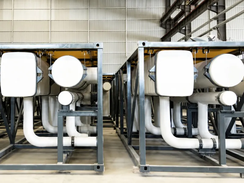
The outlets of the raw-material tanks connect to metering pumps. The preparation tanks require agitators. The buffer tanks connect to production-supply pumps, while the recovery tank receives liquid from multiple drainage points.
The interfaces, level-control logic and transfer capacities of the tanks needed to be coordinated. Otherwise, the system could experience insufficient raw-material supply, waiting time during solution preparation, inadequate buffering or delayed drainage of recovered liquid.
The complete tank system involves raw-material lines, process-water lines, supply lines, return lines, overflow lines, vent lines, drainage lines and instrument connections.
The customer required the size, orientation and elevation of every nozzle to be determined according to the equipment layout drawings. A common directional reference was established so that the tanks could connect accurately with the prefabricated piping after arrival at the project site.
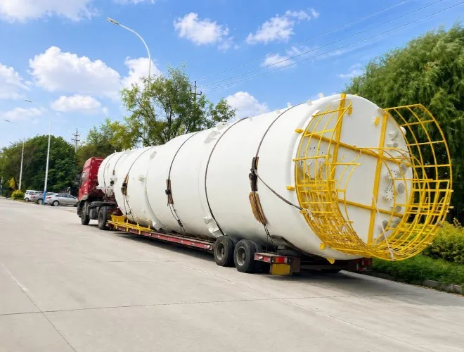
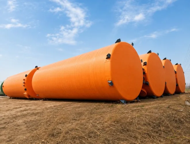
FRP tanks are relatively lightweight, but their large volume occupies considerable transportation space.
The customer required more than secure packaging. The transportation plan also needed to improve space utilization through appropriate dimensional combinations, tank nesting and phased shipment arrangements.
At the beginning of the project, Yingnai’s technical team established an individual medium-review record for each tank based on its equipment data sheet.
Material selection considered not only the normal operating concentration, but also raw-material unloading, short-term concentration fluctuations, cleaning media, operating temperature and long-term exposure conditions.
Each tank was designed with an internal corrosion-resistant laminate and an external structural reinforcement layer.
The internal wetted structure isolates the chemical medium and protects the reinforcing fibers. The external structural laminate carries the liquid load, equipment self-weight and forces generated during installation.
The raw-material tanks were designed with emphasis on long-term chemical storage and unloading conditions.
For the preparation tanks, particular attention was given to reinforcing the agitator installation areas and chemical inlet connections.
For the buffer tanks, the pump interfaces and operating liquid levels were coordinated with the supply requirements.
The recovery tank was designed with emphasis on complete drainage, cleaning and maintenance.
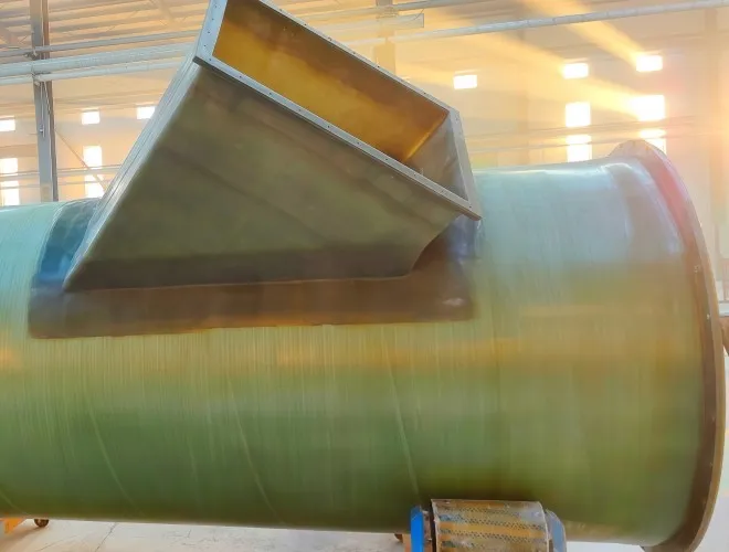
Local reinforcement was provided around manways, nozzles, level-instrument connections and other openings. Heavy valves, pumps and external piping were independently supported to prevent additional loads from acting directly on the FRP nozzles.
Based on the approved layout drawings, Yingnai established a unified orientation reference and equipment identification system for all tanks.
The nozzle schedule, flange specification, installation elevation and connection direction of each tank were confirmed individually.
During production, the technical, manufacturing and quality teams worked from the same approved drawing set, reducing the risk of interface confusion among multiple units.
All tanks, removable accessories and supporting components were clearly identified, allowing the site team to check and assemble the equipment according to the installation area and process sequence.
During batch production, Yingnai focused on the following control points:
1. Resin, glass-fiber reinforcement and auxiliary materials used for each tank
2. Impregnation quality and surface condition of the internal corrosion-resistant laminate
3. Thickness and continuity of the tank-wall structural laminate
4. Tank diameter, height, roundness and verticality
5. Nozzle orientation, elevation and flange flatness
6. Local reinforcement around agitator interfaces, tank roofs and support areas
7. Tank bottom, tank roof and nozzle transition sections
8. Equipment numbers, nameplates and site installation markings
After each tank was manufactured, the quality team inspected its appearance, principal dimensions, nozzle positions and accessory condition according to the approved drawings. Leak-tightness and other project-specific final inspections were also completed as required.
For tanks with similar dimensions, the inspection covered not only the individual equipment but also cross-checking of equipment numbers and nozzle configurations. This helped prevent confusion regarding tank duty or connection information during batch delivery.
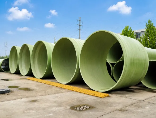
Yingnai developed an integrated transportation plan according to the diameter and height of each tank.
Where structurally and spatially feasible, smaller-diameter tanks were temporarily nested inside larger tanks to improve transportation-space utilization.
Isolation and support materials were installed between the nested tanks to prevent friction and concentrated loading during transportation.
Manway covers, spool pieces, fasteners and some removable accessories were packaged separately according to their equipment numbers.
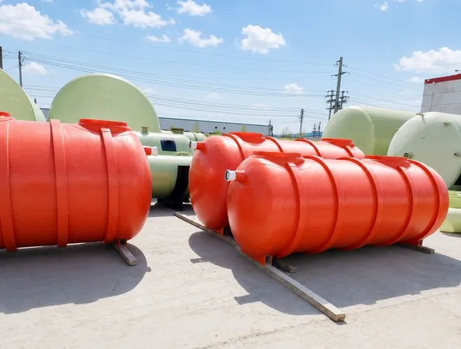
Protective structures were installed over nozzles, flanges and instrument connections. Transportation cradles were provided beneath the tanks to prevent impact or deformation during loading, unloading and long-distance shipment.
After the equipment arrived at the project site, Yingnai provided remote guidance or on-site technical support according to the customer’s requirements. The support scope included:
Checking equipment numbers and installation positions
Confirming foundation dimensions and tank orientation
Advising on lifting positions and installation sequence
Inspecting nozzle connections and external piping supports
Guiding the installation of agitators and level instruments
Reviewing site issues based on photographs, videos and measured data
The multiple FRP tanks were manufactured, inspected and delivered internationally according to their different media, process functions and interface conditions.
Together, they formed a complete system for chemical raw-material storage, process-solution preparation, buffered supply and cleaning-liquid recovery.
The project solution addressed the following key requirements:
Separate storage and independent transfer of different acidic raw materials
Metered preparation and homogenization of raw materials and process water
Continuous downstream liquid supply through dedicated buffer tanks
Reduced influence of solution preparation on production-line operation
Separate resin and wetted-laminate configurations for different media
Reduced site piping modifications through a unified nozzle reference system
Improved batch installation and commissioning through clear equipment identification
Improved international transportation-space utilization through nesting and centralized packaging
Integration of cleaning-liquid collection, reuse and downstream treatment into the process
Keywords
chemical processing project, FRP tank, FRP chemical storage tank, fiberglass chemical tank, acid-resistant tank, FRP process tank
Meta Description
A chemical processing project in Sweden used multiple customized FRP tanks to form an integrated system for acidic raw-material storage, process-solution preparation, buffered supply and cleaning-liquid recovery. This case study covers equipment configuration, process operation, corrosion-resistant design, batch manufacturing, quality inspection, international transportation and installation support.
 English