| Item | Large FRP Vessel | Selection / Engineering Note |
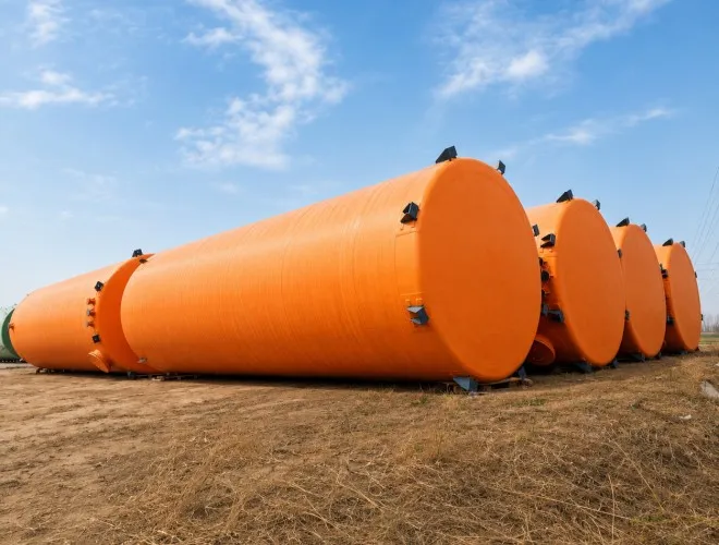
| Product Name | Large FRP Storage Vessel | Custom corrosion-resistant storage equipment |
| Typical Capacity Range | 150–2500 m³ | Other dimensions can be engineered |
| Typical Diameter Range | D 4500–15000 mm | Other dimensions can be engineered |
| Main Sizing Dimension | Cylindrical shell height H | See the three sizing-matrix sheets |
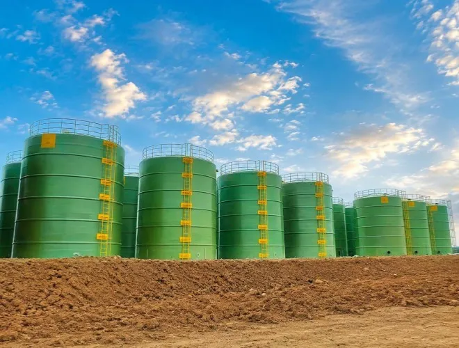
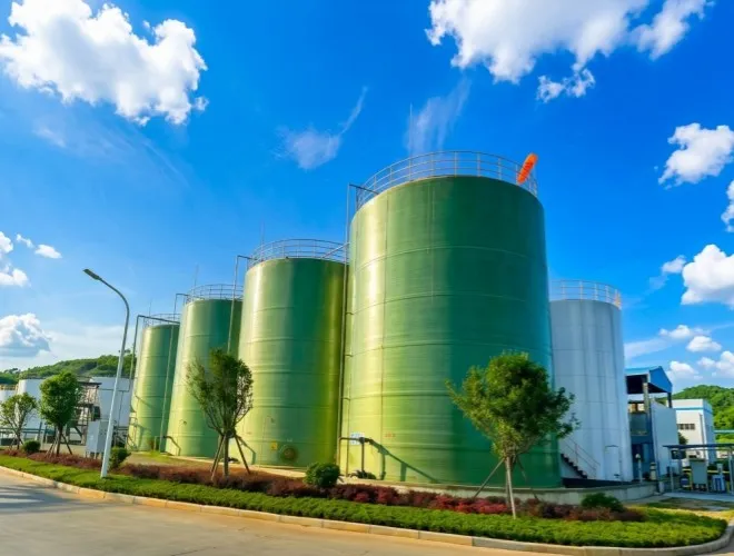
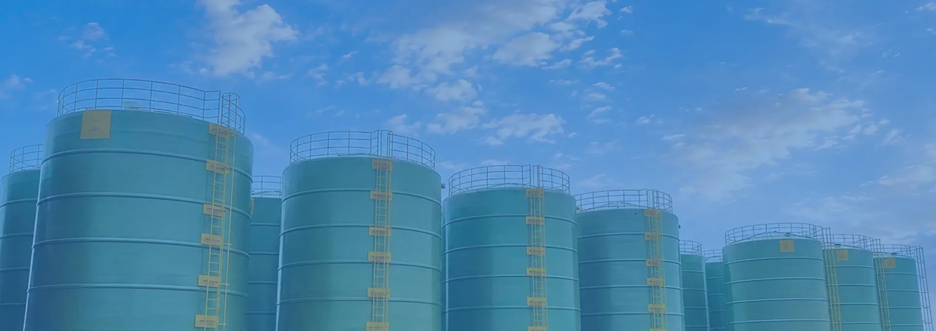
| Installation Orientation | Vertical, aboveground, generally field-fabricated | Installation method depends on site and transport limits |
| Fabrication Method | On-site filament winding or sectional field assembly | Selected according to diameter, capacity and access |
| Structural Configuration | Inner corrosion barrier, structural shell, external protection and local reinforcement | Laminate schedule is project-specific |
| Resin Options | Generally isophthalic or vinyl ester systems for industrial chemical service | Final resin must be checked against medium, concentration and temperature |
| Reinforcement | Surface veil, mat and continuous winding reinforcement; local FRP stiffeners as required | Glass type and content follow the laminate design |
| Design Pressure | Atmospheric as standard | Pressure or vacuum service requires a separate verified design |
| Operating Temperature | Designed according to resin system, medium and actual service conditions | Do not publish a single universal temperature limit without resin verification |
| Operating Medium | Bulk storage of water, wastewater, acids, alkalis, salts and industrial process liquids | Chemical compatibility review is required |
| Design Specific Gravity | Project-specific; hydrostatic load governs shell and foundation design | Customer should provide normal and maximum density |
| Corrosion Barrier | Resin-rich inner surface with chemical-resistant veil and laminate | Barrier thickness and resin are selected for the medium |
| External Protection | UV-resistant outer layer and optional fire-retardant/weathering system | Colour and protection system can be customized |
| Tank Bottom / Supports | Flat continuous bottom on reinforced concrete foundation or ring foundation | Foundation reactions must be confirmed by final design |
| Inlet and Outlet | Large nozzles, drains and process connections customized | Piping loads should not be transferred directly to the shell |
| Manhole | Multiple roof or shell manholes available | Access and maintenance requirements govern arrangement |
| Vent / Overflow | Vent, overflow and emergency relief arrangement as required | Sizing follows filling, emptying and process conditions |
| Optional Accessories | Roof, ladder, platform, guardrail, mixer support, level system and internal components | Accessory loads must be included in structural design |
| Inspection and Testing | Same, plus field-joint inspection and site hydrostatic testing where specified | Test scope follows contract and applicable code |
| Applicable References | ASME RTP-1 and project/local structural requirements where specified | Reference does not imply certification unless contractually stated |
| Installation Method | On-site winding or sectional assembly on prepared foundation | Installation manual and lifting plan should be project-specific |
| Application Fields | Large-volume chemical, water, wastewater, food, fermentation and bulk process storage | Actual suitability depends on medium and hygiene requirements |
| Customization | Diameter, height, roof, foundation interface, nozzle arrangement, platform and site-fabrication plan | Manufacture according to approved drawings |
| Required Inquiry Data | Medium, capacity, density, wind/seismic data, site access, foundation and nozzle schedule | These inputs are required before final quotation and design |


 English