This project serves a municipal wastewater collection and conveyance system in Canada. As wastewater volumes within the service area increased, the existing conveyance facilities gradually approached their design capacity during peak-flow conditions. A new pressurized pipeline was therefore required to transfer domestic sewage and wastewater from public facilities collected at a lift station to the downstream wastewater treatment system.
The pipeline route passes beneath roads, public green spaces and areas with dense existing underground utilities. Some sections are installed at considerable burial depths and are exposed to traffic loads, groundwater and seasonal temperature variations. The conveyed wastewater may contain sulfides, chlorides, suspended solids and other constituents, placing specific requirements on the internal pipe surface, joint areas and long-term operating reliability.
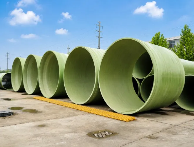
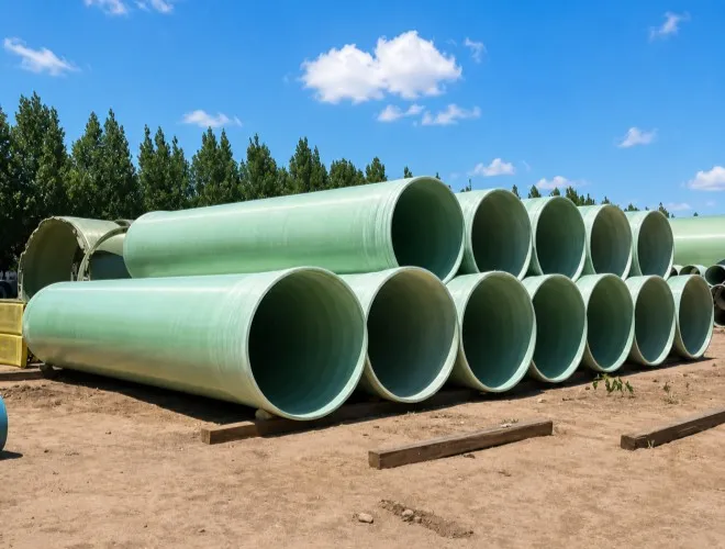
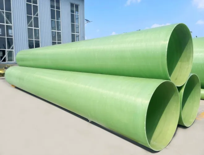
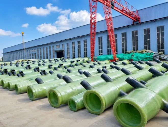
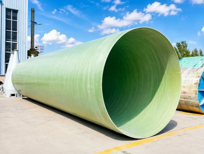
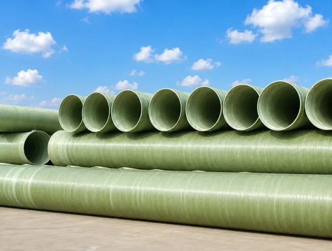
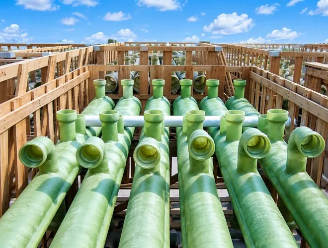
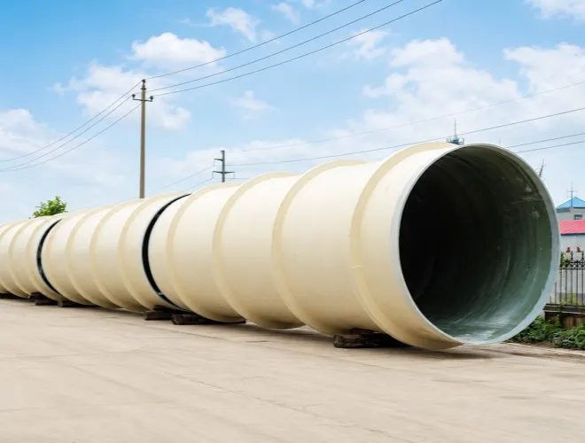
Based on the design flow, operating pressure, pipeline route, burial conditions and interface information provided by the customer, Yingnai manufactured FRP pressure pipes, elbows, tees, reducers, flanged spool pieces and connection accessories for the project. Together, these components formed a complete wastewater force main from the lift-station outlet to the downstream treatment facility.
Based on the municipal wastewater volume, lift-station operating mode and site construction conditions, the principal project configuration included:
Approximately 3,600 m of DN600 FRP pressure main
Approximately 600 m of DN400 FRP connecting and branch pipelines
Total pipeline length of approximately 4,200 m
System design conveyance capacity of approximately 1,250 m³/h
Normal operating pressure of approximately 0.55 to 0.70 MPa
Main pipeline pressure rating of 1.0 MPa
Standard straight-pipe lengths determined according to transportation and construction requirements
FRP elbows of different angles, tees and reducer sections
Flanged spool pieces, lift-station connection sections and valve connection components
Buried-pipe stiffness determined according to burial depth, soil conditions and traffic loads
Typical cover depth of approximately 2.0 to 4.5 m
The main pipeline conveys wastewater between the lift station and the downstream treatment facility, while the DN400 sections connect branch lines, valve chambers and local process facilities.
The different pipe sections were not produced using one uniform wall thickness. Yingnai configured the primary structural laminate and local reinforcement separately according to pipe diameter, pressure rating, burial depth and external loading conditions.
Wastewater from the service area first enters the lift-station wet well through the gravity sewer network. When the wet-well level reaches the preset operating point, the sewage pumps start and discharge the wastewater under pressure into the DN600 FRP force main.
Multiple pumps operate in different combinations according to changes in liquid level and flow demand. Under normal low-flow conditions, only part of the pump group operates. During peak wastewater inflow, the control system brings additional pumps online to maintain the wet-well level and required conveyance capacity.
The FRP pipeline transfers the variable lift-station discharge to the downstream treatment facility. Air-release devices are installed at pipeline high points to reduce the influence of trapped air on flow and pressure. Drain or flushing connections are provided at low points to support pipeline emptying, flushing and maintenance during shutdowns.
During pump starting, stopping or switching, the pipeline may be exposed to transient pressure variations. The system design therefore considers normal operating pressure, pump head, valve operation and pressure surges rather than selecting the pressure class solely according to steady-state flow conditions.
After conveyance, the wastewater enters the downstream inlet facilities and then passes through preliminary treatment, biological treatment and subsequent treatment processes. Within the overall municipal system, the FRP pipeline functions as an underground artery connecting wastewater collection, pumping and treatment facilities.
The composition of municipal wastewater varies with domestic water use, public-facility discharge and seasonal operating conditions. The internal surface of the pipeline remains continuously exposed to a wet environment, while some areas may also experience sulfur-containing gases and condensation.
Hydrogen sulfide is a common source of corrosion and odor in wastewater networks and can accelerate the deterioration of concrete and metallic infrastructure.
The customer required the wetted laminate of the pipeline to withstand long-term municipal wastewater conveyance and reduce maintenance associated with internal corrosion, coating deterioration and rust formation.
A wastewater force main must withstand not only the internal pressure generated by the lift station, but also external loads from soil cover, groundwater, backfill materials and road traffic.
Some deeply buried sections require increased circumferential stability. Inadequate pipe stiffness, trench width or backfill compaction could result in localized deformation, potentially affecting joint sealing and long-term system performance.
The route includes roads, existing utilities, inspection chambers and other public infrastructure, making an entirely straight alignment impractical.
The customer required elbows of different angles, reducers and non-standard connection spool pieces. These fittings also needed to connect accurately with the lift-station outlet, valves, flowmeters and downstream equipment.
The project involved a large number of pipe sections with different sizes and installation locations. Unclear pipe identification, packaging or loading sequences could increase site searching, handling and repositioning work.
The customer therefore required clear pipe numbering, connection relationships and installation documentation, allowing the construction team to organize installation section by section along the pipeline route.
At the beginning of the project, Yingnai’s technical team confirmed the conveyed medium, design flow, working pressure, transient pressure, operating temperature, burial depth and soil conditions.
The pipes were designed with an internal corrosion-resistant laminate, a structural reinforcement layer and an external protective layer.
The internal wetted structure isolates the wastewater from the reinforcement and protects the glass fibers. The structural laminate carries internal pressure, pipe self-weight and buried loads. The external protective layer provides additional protection during transportation, installation and underground operation.
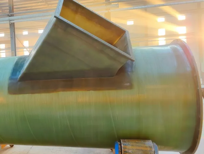
Local reinforcement was added around elbows, tees, reducer sections and flanged connections according to their loading conditions, reducing stress concentration caused by geometric transitions.
Straight pipe sections primarily use sleeve couplings with elastomeric sealing elements. This allows adjacent pipe sections to be positioned and connected efficiently while providing a limited amount of installation adjustment.
Flanged connections are used at lift-station, valve and equipment interfaces. Flange drilling, pressure class and sealing surfaces were confirmed according to the customer’s equipment data.
For axial forces generated near elbows and tees, the design documentation specified concrete thrust blocks, fixed supports or other restraint measures. This prevents the entire thrust load from being transferred directly to adjacent pipe joints.
Based on pipe diameter and structural configuration, Yingnai provided guidance covering trench preparation, bedding and backfilling.
The pipe bottom requires continuous and uniform bedding support, preventing stones or hard projections from directly contacting the pipe wall.
Side backfill is placed in layers and compacted to the required level so that external loads can be shared by the pipe and surrounding soil.
Road crossings and locally high-load sections are treated according to the construction plan through reinforced protection, casing installation or increased pipe structural class.
During batch production of the FRP pipes, Yingnai focused on the following control points:
1. Verification of resin, glass-fiber reinforcement and auxiliary materials
2. Impregnation quality and surface condition of the internal corrosion-resistant laminate
3. Thickness and continuity of the structural pipe wall
4. Internal diameter, length, roundness and end dimensions
5. Machining accuracy of joint-sealing areas
6. Geometric dimensions of elbows, tees and reducers
7. Flange flatness, bolt-hole positions and connection specifications
8. Pipe-section numbering, flow-direction markings and installation-area identification
Finished products were inspected for appearance, dimensions, structural condition and pressure-related requirements according to the project inspection plan.
For the associated fittings, interface dimensions and assembly relationships were also verified to reduce the risk of straight pipes and fittings failing to match after arrival at the construction site.
Straight pipes were loaded using layered supports and securing arrangements according to pipe diameter. Smaller-diameter pipes and selected fittings were combined within available transportation space to improve loading efficiency.
Pipe ends and sealing areas were protected. Elbows, tees, flanged spool pieces and sealing components were packaged according to their installation areas.
Each package was matched with packing documentation and corresponding pipe-section numbers to simplify site receiving and inventory control.
After the pipes arrived at the project site, Yingnai could provide remote or on-site technical support according to construction requirements, including:
Verification of pipe-section numbers and installation sequence
Confirmation of trench bedding and backfill conditions
Guidance on joint cleaning, gasket installation and pipe alignment
Inspection of elbow, tee and thrust-restraint locations
Confirmation of lift-station and valve connections
Support for hydrostatic testing and analysis of site issues
The FRP pipes and associated fittings were manufactured, inspected and delivered internationally according to the pressure, burial depth and interface requirements of the municipal wastewater conveyance system.
The completed equipment package formed a continuous pressurized pipeline from the lift station to the downstream wastewater treatment facility.
The project solution addressed the following key requirements:
Increased municipal wastewater conveyance capacity during peak-flow conditions
Reduced risk of pipe-wall corrosion caused by wastewater and sulfur-containing environments
Compliance with both internal-pressure and buried-load requirements
Adaptation to a complex underground route through customized fittings
Improved pipeline operation through air release and low-point drainage arrangements
Reduced field connection adjustments through unified interface control
Improved batch installation and construction management through pipe-section numbering
Reduced lifting and site handling requirements due to the relatively low weight of FRP piping
Keywords
FRP pipe, fiberglass wastewater pipe, municipal sewage force main, FRP pressure pipe, buried fiberglass pipe
Meta Description
A municipal infrastructure project in Canada used customized FRP pressure piping to convey wastewater from a lift station to a downstream treatment facility. This case study covers pipeline configuration, system operation, corrosion-resistant design, buried structural requirements, fitting manufacture, international transportation and installation support.
 English