In an FRP piping system, straight pipe usually accounts for most of the total length. Yet the locations where flow patterns, mechanical loads, and wear conditions become more complicated are often concentrated around elbows, tees, reducers, flanges, and other fittings.
This does not mean that fittings are inherently less reliable than straight pipe. The reason is simpler: they are asked to do more.
A straight pipe mainly carries fluid from one point to another. An elbow changes flow direction. A tee divides or combines flow. A reducer changes cross-sectional area and velocity. A flange may also provide a removable connection to equipment or another piping section.
Once the geometry changes, the hydraulic and structural conditions change with it.
For this reason, the reliability of a piping system should not be judged only by the diameter, wall thickness, and pressure rating of the straight pipe. The design, manufacture, installation, and support of FRP pipe fittings deserve equal attention.
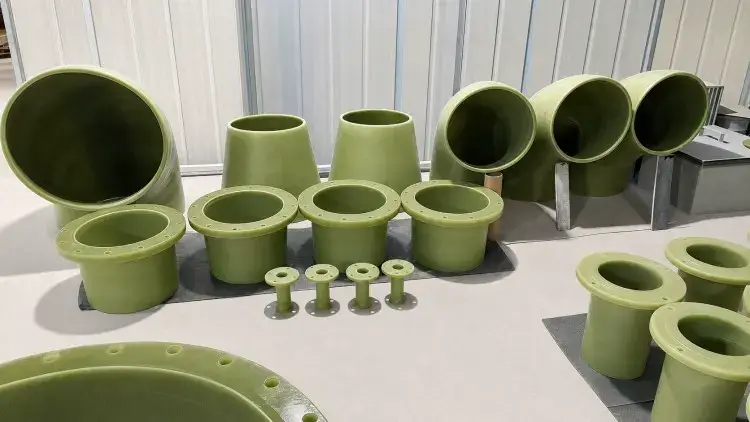
In a straight pipe, the general direction of flow remains stable. When the fluid enters an elbow, it has to change direction over a relatively short distance.
That change produces a more complex velocity and pressure distribution inside the fitting.
For clean liquids, the main effects are usually local hydraulic loss and changes in mechanical loading. If the fluid contains sand, mineral particles, crystals, sludge, or other suspended solids, the outside radius of the bend may also experience more concentrated particle impact.
This is why the operating condition of an elbow can differ significantly from that of the straight pipe connected to it.
In slurry, industrial wastewater, mineral-processing, or solids-bearing chemical service, several factors become especially important:
solids concentration;
particle size and hardness;
flow velocity;
bend radius;
operating temperature;
frequency of start-up and shutdown.
Higher velocity, harder particles, and tighter changes in direction can increase local wear.
For abrasive service, the solution may involve a larger bend radius, an enhanced wear-resistant inner layer, or a fitting specifically designed for the expected erosion conditions.
FRP is a designable composite material. Its load-carrying behavior depends on reinforcement direction, reinforcement content, resin system, and laminate construction.
A straight cylindrical pipe has a relatively regular geometry, so hoop and axial stresses can be handled in a predictable way.
Elbows, tees, and reducers are different.
Their geometry changes the way loads move through the component.
For example:
an elbow changes the direction of pressure thrust;
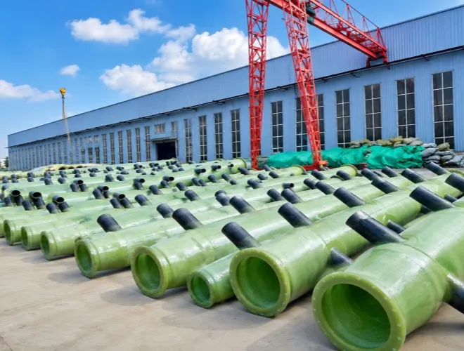
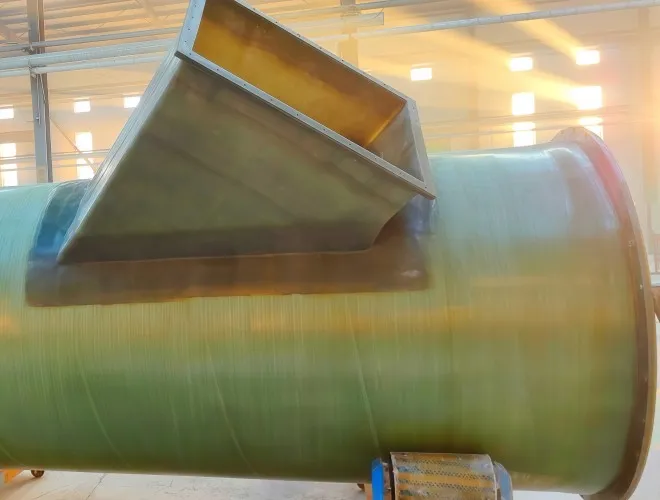
a tee introduces a branch opening into the main pipe wall;
a reducer changes cross-sectional area and local flow conditions;
a flange transfers bolt and gasket loads into the composite structure.
This means a fitting cannot simply be treated as “a straight pipe bent into another shape.”
A tee creates an interruption in the continuous wall of the main pipe.
The branch area has to maintain sealing while also transferring loads between the main run and the branch connection.
Local reinforcement is therefore often required around the branch area.
If a heavy valve, unsupported branch pipe, or piece of equipment is then attached to the branch, the load can increase further.
The fitting design and the surrounding support arrangement should therefore be considered together.
A reducer changes the internal flow area.
That can alter velocity, local pressure distribution, and hydraulic losses.
A very abrupt reduction can create stronger turbulence, while a gradual transition allows the flow to adjust more smoothly.
Reducer length, transition geometry, and installation location should therefore be considered as part of the overall hydraulic design rather than treated as a purely dimensional issue.
Selecting the correct corrosion-resistant resin for the straight pipe does not automatically make the entire piping system chemically compatible.
The process fluid also passes through elbows, tees, reducers, flanges, and joints.
If one fitting uses a different resin system, an unsuitable corrosion barrier, or poor curing, that location can become the weak point in an otherwise well-selected system.
The wetted surfaces of fittings should therefore be evaluated using the same service conditions as the main pipe, including:
chemical composition;
concentration;
normal and maximum temperature;
design pressure;
presence of abrasive particles.
This is especially important in acid, alkali, high-salinity wastewater, and mixed chemical service.
The question should not simply be:
“Is this an FRP fitting?”
It should be:
“Is the resin system and internal corrosion-resistant construction of this fitting suitable for the actual medium?”
Industrial piping systems may use elbows with different bend radii.
A tighter bend can save installation space, but it forces the fluid to change direction more abruptly.
A larger-radius bend requires more room, but the change in direction is more gradual.
For clean fluids, the decision may mainly involve available space and hydraulic loss. For abrasive or solids-bearing fluids, bend radius can also influence where particles strike the internal surface and how concentrated the wear becomes.
There is therefore no single bend radius that is ideal for every FRP piping system.
The selection should consider:
fluid characteristics;
solids loading;
velocity;
pipe diameter;
available space;
fabrication requirements.
A suitable FRP elbow should be selected as part of the piping system, not simply by matching diameter and angle.
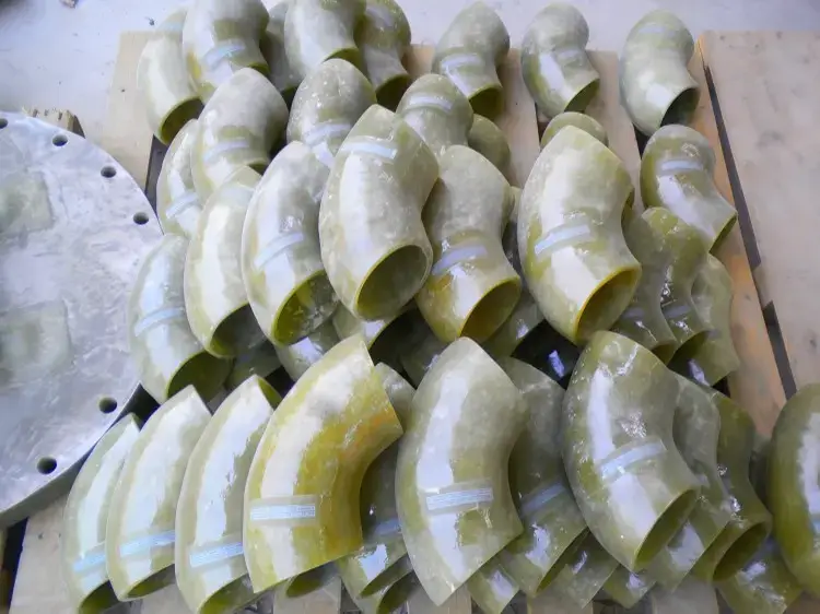
Fittings do not operate independently of their connections.
Elbows, tees, and reducers must eventually be connected to straight pipe. Depending on the piping system, those connections may use flanges, adhesive sockets, couplings, or field-laminated joints.
A properly manufactured fitting can still become part of an unreliable system if the joint next to it is poorly designed or installed.
Typical problems include:
flanges pulled into alignment with excessive bolt force;
inadequate surface preparation before field lamination;
adhesive joints loaded before sufficient curing;
poor support locations that transfer excessive load into a fitting or joint.
For this reason, fittings and joints should be considered together.
The fitting changes the geometry and flow path. The joint integrates that fitting into the complete pipeline.
Elbows and tees are frequently located near changes in direction, branch connections, valves, or process equipment.
These are already areas where loads tend to accumulate.
If the support arrangement is poor, pipe weight, valve weight, thermal movement, and installation misalignment can add further stress.
Common problems include:
heavy valves hanging directly from an FRP fitting;
long unsupported pipe spans;
thermal movement being restrained at one elbow or flange;
a branch pipe pulling continuously on a tee to compensate for poor alignment.
A good support arrangement should allow the pipe, fittings, and equipment connections to work naturally.
A fitting should not be forced to perform the job of a missing support or an incorrect anchor.
When pressurized fluid changes direction, it generates thrust forces.
Elbows, tees, reducers, closed ends, and other changes in the flow path can become locations where these forces are concentrated.
For pressure FRP piping, it is therefore not enough to confirm that the fitting can withstand the internal pressure.
The system must also define how the resulting thrust will be resisted.
Depending on the piping layout and joint type, the load may be managed through:
anchors;
fixed supports;
thrust restraint;
structurally restrained joints;
other engineered support arrangements.
The important question is not which restraint method is universally best.
The important question is:
Where will the force go?
If that load path has not been defined, pressure thrust may be transferred into fittings, joints, or equipment nozzles that were never intended to carry it.
Straight pipe has a regular geometry, which makes many manufacturing processes easier to control consistently.
Elbows, tees, and reducers have more complicated surfaces and transitions.
Fiber placement, local reinforcement, resin wet-out, overlap, and curing all require greater attention.
Quality evaluation should therefore look beyond whether the outside surface appears smooth.
Important points include:
continuity of the internal corrosion-resistant surface;
complete resin wet-out;
absence of excessive voids or dry reinforcement;
proper bonding between laminate stages;
correct reinforcement around openings and transitions;
dimensional accuracy for field connection.
In chemical and industrial piping, these complex geometric areas often have to resist chemical exposure, pressure, and external mechanical loads at the same time.
That makes manufacturing consistency especially important.
After installation, inspection should not focus only on long straight pipe runs.
Elbows, tees, reducers, flanges, and field joints deserve particular attention before and after pressure testing.
Inspectors may look for conditions such as:
unusual cracking;
joint leakage;
visible deformation;
flange misalignment;
fittings being pulled by connected piping;
poor or displaced supports;
localized wear in solids-bearing service.
For operating systems, inspection priorities should also reflect the actual service conditions.
If a pipeline continuously carries abrasive slurry, for example, elbows may deserve more frequent attention than ordinary straight pipe sections.
Inspection strategy should therefore follow where the system experiences the most demanding combination of flow, load, corrosion, and wear.
Looking at an elbow by itself, it is easy to focus only on angle, diameter, and wall thickness.
Once that elbow is placed back into the full pipeline, the questions become more practical:
What fluid is being transported?
What is the operating velocity?
Are solids present?
What is the working pressure?
How is the fitting connected?
Is there a nearby valve or equipment nozzle?
How is the pipe supported?
Will temperature changes cause movement?
These factors define the real service condition of the fitting.
When specifying fittings, it is therefore better to provide more than a quantity such as “ten 90-degree elbows.”
Useful project information includes pipe diameter, fluid composition, operating temperature, pressure, connection method, and major layout conditions.
This allows the fitting construction to remain consistent with the rest of the FRP pipe system.
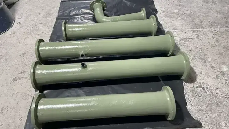
In many FRP piping projects, considerable attention is given to the straight pipe: resin type, wall thickness, pressure rating, and diameter.
Fittings are sometimes treated as secondary accessories.
In reality, fittings are often located exactly where the system changes most.
Flow direction changes there. Pipe diameter changes there. Branches begin there. Equipment connections are often located there.
As a result, fittings may experience hydraulic, structural, installation, and maintenance demands at the same time.
For Yingnai piping projects, elbows, tees, reducers, and other fittings can be considered using the same service basis as the straight pipe, including fluid composition, concentration, temperature, pressure, velocity, solids content, joint type, and support conditions.
A reliable FRP piping system is not created by making the straight pipe strong enough.
It is created when straight pipe, elbows, fittings, joints, and supports are designed to work together as one system from the beginning.

 English